10Scene Programming
Configuration with GeNetix Products (GN5, GN10, GN10P, GN10R and Gateway)
When connected 10Scene Wall Plates to the GN5, GN10, GN10R and GN10P Nodes, then 10Scene Wall plate be used to either trigger 10 Static scenes on the node itslef. In this configuration the GeNetix Node could be used as a simple houselight controller, where when a Lighting Console is connected and outputting Art-Net/sACN to the Node the Scenes can be set to auto disable. The other option is to use the GeNetix Node as a 'Gateway' converting from the 10Scene Protocol to ChamSys Remote protocol, in this mode a 10Scene Wall Plate connected to the GeNetix Node, could then be used to trigger Playbacks/Executes on a MagicQ/QuickQ Console. In this configuration the GeNetix Node is acting as the 'Gateway' or protocol converter allowing this.

Using 10Scene Wall Plates with a GeNetix Node to trigger Local Scenes on the Node
Connect the 10Scene Wall Plate to the GeNetix Node per the wiring shown in the Chapter above.
On the GeNetix Node, in the '10Scene' Menu select one of the following options:
-
Scenes Optional (Default)
-
Only Scenes
When set to Scenes Optional scenes can be activated and deactivated as required, an active scene is not always required. e.g. it’s possible to turn off all scenes.
When set to Only Scenes, one Scene is always active. This useful when the install always requires a Scene to be active e.g. lights always on.
Scenes can be stored on the GeNetix nodes by either sending scenes from a MagicQ/QuickQ Console to the node, or via using the Nodes webserver or front display to 'snapshot' incoming DMX from an external console and store these as Scenes.
Using 10Scene Wall Plates with a GeNetix Node in Gateway mode to trigger scenes on a MagicQ/QuickQ console.
On the GeNetix Node, in the '10Scene' Menu select the Gateway option. Note the GeNetix Node must be in the same IP address range and Subnet as the MagicQ/QuickQ console. For example if the console IP address is 10.0.0.50 Subnet 255.0.0.0, the Node should be in the same range - for example it could be set to 10.0.0.60 Subnet 255.0.0.0
For configuration of 10Scene Wall Plates in MagicQ/QuickQ Software see the chapters below.
Configuration with QuickQ Products
QuickQ offers four operation modes for 10Scene Wall Plates:
-
10Scene toggles playbacks 1-10 on and off, in this mode 10Scene wall plates will toggle on and off playbacks recorded on right-hand side of the console, these can be either a cue or a chase.
-
10Scene toggles executes 1-10 on and off, in this mode 10Scene wall plates will toggle on and off the first 10 execute cues recorded in the Execute Window.
-
10Scene controls execute in zones set by groups
-
10Scene controls executes in rows, in this mode 10Scene wall plates will toggle executes in zones defined by rows. The execute grid must be 10 cells wide, for example: 10x1, 10x6 or 10x10.
QuickQ supports up to 10 Zones.
Sequential Zones can be joined together in the 10Scene Settings Window, for example Zone 1 and 2 joined allowing all 10 zones to be joined together if desired. This is useful for spaces like a ballroom, where there may be a temporary airwall fitted and have multiple entrance doors. Zones can be joined allowing the room to operate as 1. When Zones are joined 10Scene Wall Plates would control all linked zones. It’s possible to use contact triggers to automate the joining and splitting of Zones.
Choose the option you want in the 10Scene Window Settings tab.

Gateways
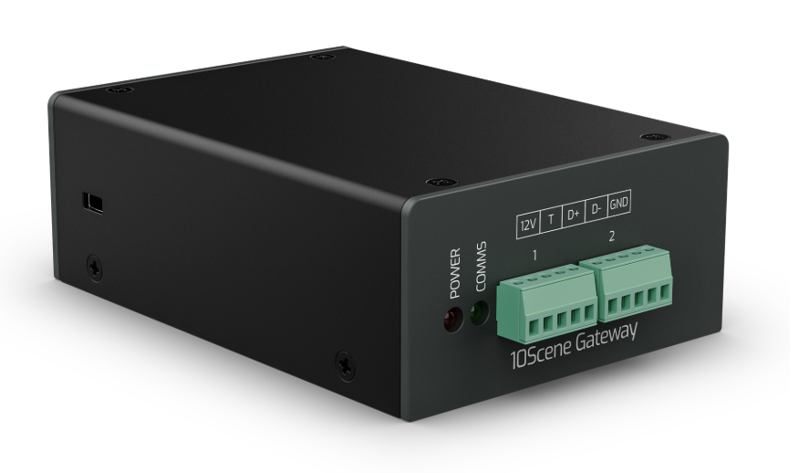
GeNetix Gateway interfaces are used to connect 10Scene wall plates to a QuickQ Console or additional 10Scene wall plates to the QuickQ Rack. Each Gateway has 2 10Scene sockets to connect up to 20 10Scene wall plates (10 per socket) and 2 contacts.
The Gateways tab displays Gateways that are connected to the system and allows for configuration of these interfaces.
The Gateway name, IP address and subnet mask can be configured from the Gateways tab using the Action menu.
The IP address of the console can be set in the Network Settings Window.
|
10Scene Gateways must be enabled in for Gateways to work. |
Configuring 10Scene Wall Plates
10Scene Wall Plates can be connected directly to the QuickQ Rack and QuickQ DIN’s via the 10Scene Ports on these units. The GeNetix 10Scene Gateway, GeNetix GN5, GN10, GN10P and GN10R can also be used to connect 10Scene Wall Plates to QuickQ Consoles.
QuickQ Consoles support up to 10 Zones and up to 4 10Scene Ports in the Ecosystem. Each 10Scene Port can have up to 10 10Scene Wall Plates daisy chained to it.
Each 10Scene Wall Plate has a unique ID. 10Scene Wall Plates ship with a default factory ID. When using Zones with QuickQ, the 10Scene Wall Plate ID = Zone ID.
Setting 10Scene Wall Plate IDs
Each 10Scene Wall Plate in the system should have a unique ID. Where Zones are not being used, for example when 10Scene Wall Plates are used to toggle on and off Playbacks 1-10 then it is not necessary to change the 10Scene Wall Plates from their factory ID.
Setting the 10Scene Wall Plates ID requires the system to be in 'Set 10Scene Panel Zone ID’s' Mode. This is set from within the 10Scene Settings Window on the QuickQ consoles. Once this option has been enabled then each wall plate in the system will Flash all buttons together and then report its ID.
To change the 10Scene Wall Plate ID Press Keys 1, 6, 5, 10 together quickly, then enter the ID/Zone ID to be set on the 10Scene Wall Plate. The 10Scene Wall plate will then flash all LEDs and then show the new programmed ID.
Once all 10Scene Wall Plate ID’s have been set, toggle off 'Set 10Scene Panel Zone ID’s' from the QuickQ software.
If a 10Scene Wall plate has previously had an ID set, then it must first be reset in order to take a new ID. Place the system into 'Set 10Scene Panel Zone ID’s' Mode and then press keys 2, 7, 4, 9 together, following by 1, 6, 5, 10 together followed by the new ID to be set. The 10Scene Wall plate will then flash all LEDs and then show the new programmed ID.
Alternatively via the QuickQ software it is possible to reset all connected 10Scene Wall Plates to their factory ID’s by using the 'Reset all 10Scene Panels to Factory ID’s' button within the 10Scene Settings Window.
Configuration with MagicQ Products
MagicQ supports 10Scene Wall Plates and 10Scene Gateways, enabling up to 50 different zones of 10Scene operation and trigger inputs.
10Scene supports ten scenes (MagicQ Cues) programmed onto 10 buttons which can be activated and released by pressing the buttons. In addition the level of the programmed Cue can be decreased and increased by pressing and holding the buttons for 1 second or more.
10Scenes can operate in a simple mode with minimal configuration, or in an extended mode with manual configuration per Zone.
10Scene Wall Plates are connected to MagicQ via one or more 10Scene Gateways, via 10Scene ports on GeNetix GN5/GN10 or via the 10Scene ports on MagicQ Rack, MagicQ DIN and MagicQ MQ250M.
MagicQ includes a demo show ZoneDemo.shw for training. After loading the show you should set the 10Scene action setting as this is a console setting and will not be set when loading the show.
Note 10Scene Gateways and wall plates do not provide any unlocking to MagicQ PC Systems, which is required to use 10Scene on PC systems.
10Scene Ports
Each 10Scene port supports up to ten 10Scene Wall Plates or 10Scene Contacts and a single remote input trigger. It is possible to use the 10Scene Wall Plates, the 10Scene Contact and the remote input trigger simultaneously.
Up to ten 10Scene devices are supported per 10Scene port - this can include a mixture of 10Scene Wall Plates and 10Scene Contacts.
Programming 10Scene Wall Plate IDs
The ID is factory assigned in the range 32768 to 61439. Users can change the ID to anything in the range 1 to 10000. All other IDs are reserved.
To change the ID the 10Scene Wall Plate must be connected to a MagicQ system with a 10Scene port or to a 10Scene Gateway support. In Setup, View Settings, Ports set 10Scene to Inbuilt if using a direct port, or Inbuilt and Gateway if using a 10Scene Gateway.
In MagicQ 10Scene Wall Plates are managed through the Macro Window, View Autom, View 10Scene. A list of detected 10Scene Wall Plates are shown, together with their current ID and firmware.
To identify a 10Scene Wall Plate move the cursor to the required row and press ENTER on column 1. This will turn all the buttons on the 10Scene to red. Press ENTER again to stop identifying, or press ENTER on another 10Scene to identify that 10SCene instead.
To check the IDs of individual Wall Plates press the PROG 10SCENE soft button. This puts all the 10Scene Wall Plates into a mode whereby they display their ID as a sequence of digits. The sequence starts with all buttons blue and then lights each LED in turn for each digit. Buttons 1 to 9 represent the digits 1 to 9 and 10 represents 0. Press PROG SCENE again to exit this mode back to normal.
To change the ID of the 10Scene, then it is necessary to first reset it back to its factory ID if it has been changed before. Press PROG 10SCENE to enter the programming mode, and then press the RESET ID button and confirm yes. The 10Scene should now change to display its factory ID.
Alternatively press PROG 10Scene and on the 10Scene Wall Plate that you wish to reset to factory, press and hold buttons 2,4,7 and 9. The 10Scene Wall Plate will then return to factory ID and will display the factory ID.
If you wish to reset all connected 10Scene Wall Plates then press SHIFT and RESET ALL IDS instead, and all 10Scene Wall Plates will be reset and then display their original factory IDs.
To program an individual 10Scene go into PROG 10SCENE mode and on the 10Scene Wall Plate press and hold buttons 1,5,6 and 10. The 10Scene Wall Plate should change to all buttons blue. Now enter the required new ID using the buttons on the 10Scene Wall Plate. You can enter up to 5 digits. It is not necessary to enter leading 0s - for example to program the 10Scene Wall Plate to ID 1 simply press 1, to program to ID 23 press 2 and then 3. After two seconds the 10Scene will reprogram its ID and if successful display the new ID.
If an invalid ID is entered or no buttons are pressed within 20 seconds then all LEDs briefly show red to indicate an error and then return to displaying the current ID.
When in programming mode any 10Scene Wall Plate that is at its original factory ID can be programmed to a new ID - it is not necessary to enter and exit the programming mode. Note however, that if an ID is incorrectly set then it must be first reset to factory before changing to the correct ID.
When all programming is complete then exit programming mode by pressing PROG 10SCENE again.
10Scene Enable
To enable 10Scene Wall Plates set the 10Scene enable within MagicQ under Setup, View Settings, Ports to Inbuilt and Gateway or Inbuilt, Gateway, Remote.
When set to disabled, there is no communication with 10Scenes Wall Plates and remotes. 10Scene zones can still be used internally through automations and macros if the 10Scene action or 10Scene zones are configured.
10Scene Action
The 10Scene action is configured in Setup, View Settings, Ports, 10Scene action.
PB1 to 10 |
All 10Scenes control PB1 to PB10 |
Exec 1 |
All 10Scenes control Exec Grid 1, items 1 to 10 |
Exec 1 Multi |
10Scenes with Zone IDs 1 to 10 control Exec Grid 1, Zone ID1 controls item 1 to 10, Zone ID2 controls 11 to 20, etc… |
Exec 1 Groups |
10Scenes control Exec Grid 1, items 1 to 10, but using Groups named with the Zone ID to determine which heads they control. |
Exec Grids |
10Scenes control Exec Grids - Zone ID 1 controls Exec Grid 1, Zone ID2 controls Exec Grid 2, etc… |
Custom |
The action for each zone is configured separately using the Type, P1 and P2 fields in Macro, View Zone |
The state of the Zones is shown in Macro, View Zone. The Zone Type field in this window should be set to "Action" for all Zones, except when using Custom action.
PB1 to 10
All 10Scene Wall Plates control PB1 to PB10. Pressing a 10Scene button activates the Playback at 100%. Pressing again releases the Playback.
The 10Scene ID is not used. Regardless of their ID, all 10Scene Wall Plates control the 10 playbacks or the first 10 items on Exec Grid 1 respectively. The IDs can remain at factory settings.
Exec 1
All 10Scene Wall Plates control items 1 to 10 in Exec Grid 1. Pressing and releasing a 10Scene button has the same effect as pressing and releasing in the Execute Window. Items in the Execute window can be set to toggle (normal) or to flash.
The 10Scene ID is not used. Regardless of their ID, all 10Scene Wall Plates control the 10 playbacks or the first 10 items on Exec Grid 1 respectively. The IDs can remain at factory settings.
Exec 1 Multi
All 10Scene Wall Plates control Exec Grid 1 with the Zone ID determining which items are controlled. Zone ID1 controls item 1 to 10, Zone ID2 controls 11 to 20, etc…
By default the ID of the 10Scene Wall Plates maps directly to the Zone ID with ID1 to ID50 being supported - Wall Plate ID1 corresponds to Zone 1, Wall Plate ID2 corresponds to Zone 2. The mapping of IDs can be modified by configuring the Min and Max fields in the Zone data.
ID 10000 is also supported to control all zones. A Wall Plate with this ID will show a button active if that button is active on any of the Zones 1 to 10 and there is a 10Scene Wall Plate detected for that Zone or a Group set up for that Zone.. When a button is pressed on that Wall Plate, if that button is active on any of Zones 1 to 10 then it will deactivate all items for that button, otherwise it will activate all items for that button. For example, pressing button 2, when Exec Grid item 12 is active will cause Exec Grid items 2,12,22,32,42,52,62,72,82,92 all to be released.
Exec 1 Groups
MagicQ handles activation of the Cues in the Exec Grid 1 based on Groups. MagicQ handles converting the Cues to only affect the heads in the specific group for the zone. Cues are expanded to include all the heads in the Group to make it simple to program and to make the system expandable without having to reprogram Cues.
Groups must be created for each zone with the Group names containing the word "Zone" followed by the zone ID - for example "Zone 1", "Zone2". Capitalisation does not matter. There can be further data after the Zone data such as "Zone 1 Room 21" - this is useful for the 10Scene app which displays Zone names.
It is important to ensure that there is only one Group with each Zone ID - if you have multiple Groups e.g. two Groups named "Zone 1" then it will use the Group with the highest group ID.
By default the ID of the 10Scene Wall Plates maps directly to the Zone ID - with ID1 to ID50 being supported - Wall Plate ID1 corresponds to Zone 1, Wall Plate ID2 corresponds to Zone 2. The mapping of IDs can be modified by configuring the Min and Max fields in the Zone data.
ID 10000 is also supported to control all zones. A Wall Plate with this ID will show a button active if that button is active on any of the Zones 1 to 50 and there is a 10Scene Wall Plate detected for that Zone or a Group set up for that Zone.. When a button is pressed on that Wall Plate, if that button is active on any of Zones 1 to 50 then it will deactivate all items for that button, otherwise it will activate all items for that button. For example, pressing button 2, will cause Exec Grid item 2 to be activate and released for all Zones.
In this mode Exec Grid 1 in the Execute Window will not show active, as there are multiple different copies of the Exec Grid 1 in action, one for each Zone (Group). It is possible to see the state for a particular zone in Macro, View Zones. In this mode activating items 1 to 10 in Execute Grid 1 by pressing in the Window or using macros/automs will activate the original Cue containing all its heads, independently of the activation of the separate zone copies - therefore you may end up with both the original Exec Grid 1 item and the copy active at the same time.
Note that MagicQ makes converts from the original Cue to the Group using an intelligent copy. The original Cue does not need to contain the Heads from the new Group - MagicQ will try to copy from any attributes from other heads in the original Cue. This is beneficial when each Zone has different fixture types.
When using multiple different fixture types, it is recommend to program all required attributes into the original Cue for each head type rather than relying on default attributes - e.g. start programming with LOCATE. This prevents MagicQ copying attributes that are not in the original Cue from other fixtures that are in the original Cue.
Exec Grids
The 10Scene Wall Plates work in zones with each Zone controlling items 1 to 10 of an Execute Grid. Zone 1 controls Grid 1, Zone 2 controls Grid 2.
By default the ID of the 10Scene Wall Plates maps directly to the Zone ID - with ID1 to ID50 being supported - Wall Plate ID1 corresponds to Zone 1, Wall Plate ID2 corresponds to Zone 2. The mapping of IDs can be modified by configuring the Min and Max fields in the Zone data.
ID 10000 is also supported to control all zones. A Wall Plate with this ID will show a button active if that button is active on any of the Zones 1 to 50 and there is a 10Scene Wall Plate detected for that Zone or a Group set up for that Zone. When a button is pressed on that Wall Plate, if that button is active on any of Zones 1 to 50 then it will deactivate all items for that button, otherwise it will activate all items for that button. For example, pressing button 2, will cause item 2 to be activate and released for all Execute Grids 1 to 50.
Custom
When 10Scene action is set to Custom the function of the Zone is determined by the Type field.
When set to Playback, the Zone will control 10 playbacks starting from the playback specified by P1.
When set to Exec Grid, the Zone will control items 1 to 10 of the Exec Grid with Grid ID set by P1.
When set to Action the Zone will not control anything.
Joining Zones
When 10Scene action is set to Exec 1 Groups, Exec 1 Multiple, Exec Grids or when zones are configured individually to control an Execute grid using a group then it is possible to join zones together. When two or more zones are joined together they operate as one zone. All Cues are expanded to include all heads of the group from each zone that is joined together.
In manual mode any zone can be joined to any other by setting the required zone to join in the Join Zone field and setting the Zone Switch to Joined.
When using Exec 1 Groups a zone can only be joined to the previous zone - i.e. Zone 2 can be joined to Zone 1, Zone 3 can be joined to Zone 2. The Zone Switch field is used to Join this zone.
In manual mode the joining of zones can be temporarily enabled and disabled for each zone.
The Zone Switch can also be operated from an automation, enabling automatic operation from a remote input. In Macro, View Autom insert an automation of Type Remote, and with Function set to Zone Switch.
When joining and separating zones the Execute state from the joined/separated from zone is maintained and expanded to the newly joined or newly separated zone.
The joining and separation of zones will only affect the zones that are part of the join/separate. All other zones will continue to operate without interruption, even if they themselves are made of several zones joined.
The Zone Switch can also be added to the Execute windows - ASSIGN SPECIAL, select 10SCENE ZONE and enter the Zone ID. The Zone Switch item in the Execute window shows active when the Zone Switch for that zone is set to joined. The text of the item indicates which Zone it is joined to. Pressing the item will change the state of the Zone Switch.